Once you're receiving signals with your SDR or replaying an IQ file, the Demodulation Tab allows you to actually listen to and fine-tune a specific signal. This is where you select the demodulation mode (like AM or FM), adjust demodulation parameters and the audio level.
Picking the correct demodulation mode is absolutely essential. If you're not using the right mode for a given signal, the result will be distorted audio — or just static. The demodulator is responsible for decoding how the original audio or data is embedded in the radio signal, and using the wrong one is like trying to play a vinyl record with a laser pointer — you won’t get music, just noise.
Use the dropdown menu at the top right to select your desired demodulation mode. The app supports:
Each mode is used in different parts of the spectrum, and often the modulation type can be guessed by frequency (use a band plan) or visual signature in the FFT/waterfall. See section Choosing the Right Demodulation Mode for more information.
The channel frequency determines at which frequency the demodulator operates. This is different from the source frequency which selects the center of the captured spectrum. The channel frequency may be choosen anywhere inside the received signal spectrum which is centered around the signal frequency (plus/ minus half of the sample rate in Hz)
There are several ways to set the channel frequency:
!!! tip "Quick Tuning" The tuning wheel is great for small frequency changes. For larger jumps, it's faster to type the frequency or drag the selector in the FFT plot. It is possible to type a frequency which lays outside of the currently received spectrum. RF Analyzer then automatically retunes the SDR if possible.
The Squelch sets a minimum signal strength (threshold) required for audio to be heard. This helps cut out background noise when no active signal is present. By default, the squelch setting is disabled, which means that audio demodulation is always active independend from the signal strength. Once enabled, the squelch indicator apears in the channel selector of the FFT plot.
The squelch can also be changed by sliding the green/red drag handle on the squelch indicator in the FFT view up or down. The indicator turns green if the current signal strengh (inside the channel bandwidth) is above the squelch threshold (demodulation active). Otherwise the indicator turns red and demodulation stops.
The squelch can also be used to automatically start and stop the recorder (see Recording Options).
At the bottom of the tab, you'll find a toggle switch labeled "Keep Channel Centered".
This gives you flexibility in how you want to interact with the spectrum display - either keeping the selected signal in the spotlight, or keeping a broader overview of the band.
Here are multiple ways to figure out which demodulation mode to use:
Used for:
Typical bandwidth: 6-10 kHz
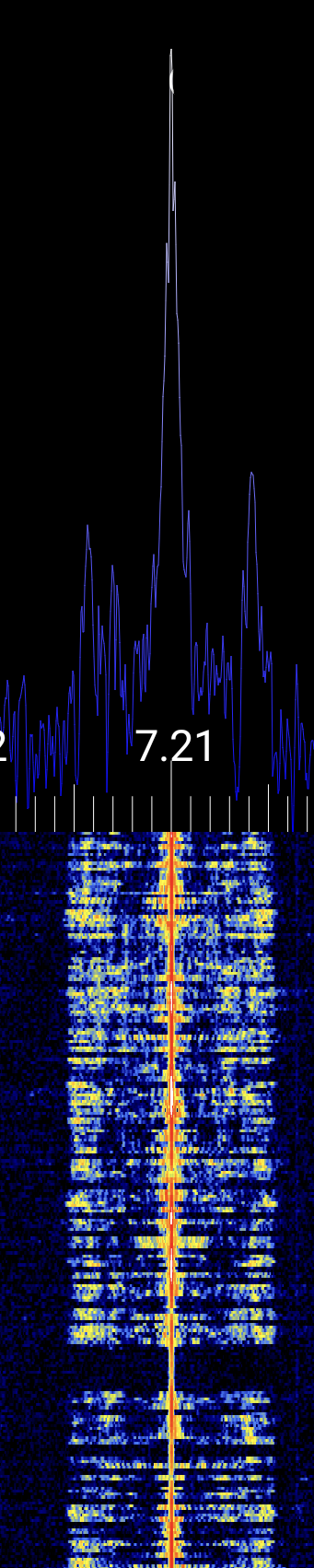
Visual signature:

Used for:
Typical bandwidth: 12.5-25 kHz
Visual signature:
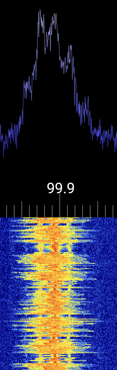
Used for:
Typical bandwidth: 100-200 kHz
Visual signature:
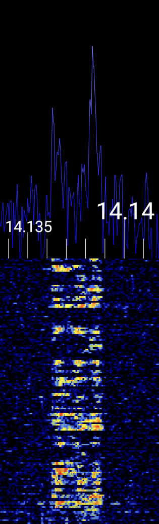
Used for:
Typical bandwidth: 2.4-3 kHz
Visual signature:
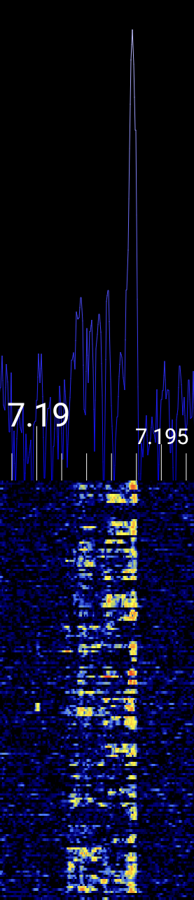
Used for:
Typical bandwidth: 2.4-3 kHz
Visual signature:
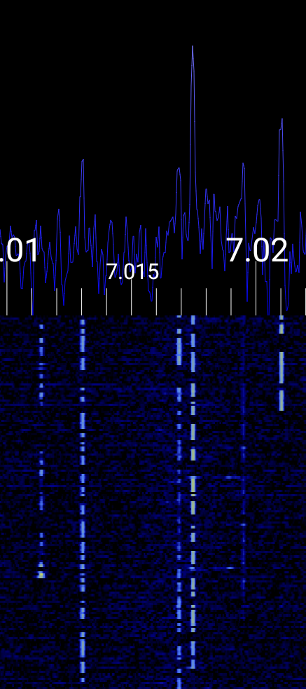
Used for:
Typical bandwidth: ~100 Hz
Visual signature:
If you're unsure about the type of signal you're observing, the following resources can assist you in identifying various RF signals, including analog audio:
Signal Identification Wiki A comprehensive community-driven guide featuring audio samples and waterfall images for a wide range of signals: sigidwiki.com
HFUnderground Signal Identification
Focused on HF and MW bands, this wiki includes detailed entries with mode, frequency, bandwidth, and visual characteristics:
hfunderground.com
Tektronix eGuide to RF Signals
Offers insights into interpreting spectrograms and understanding signal behavior over time:
Tektronix eGuide to RF Signals
Understanding the RF Spectrum - Visual Guide
A YouTube video that provides a visual walkthrough of the RF spectrum and common signal types.
Watch on YouTube
Now you are able to demodulate audio signals. Developing a good intuition of recognizing signal modulation settings by analyzing the FFT and waterfall comes naturally with time! A good way to practice is to record a brief period of IQ samples on an Amateur Radio band and replay it in a loop. Then it is easy to experiment with the various demodulation settings. Head over to the Recording section!